Precise electrode placement is the cornerstone of diagnostic electrocardiography, ensuring that the heart’s electrical activity is recorded accurately for clinical analysis. The diagram illustrates the standard configuration for a 12-lead electrocardiogram (ECG), utilizing a combination of limb leads and precordial (chest) leads to create a three-dimensional view of cardiac function. By adhering to specific anatomical landmarks, healthcare professionals can minimize artifacts and prevent misdiagnoses related to arrhythmias or ischemic events.
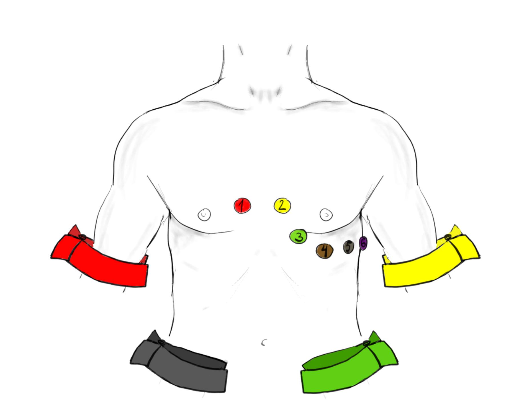
1 (V1 Electrode): This precordial electrode is placed in the fourth intercostal space at the right sternal border. It primarily monitors the right ventricle and is essential for identifying right bundle branch blocks and distinguishing between different types of tachycardias.
2 (V2 Electrode): Located in the fourth intercostal space at the left sternal border, directly across from V1. This lead provides a view of the ventricular septum and, when analyzed with V1, helps visualize the anterior wall of the heart.
3 (V3 Electrode): This electrode is positioned midway between the V2 and V4 landmarks, sitting over the interventricular septum. It represents the transitional zone of the heart’s electrical field, bridging the gap between the right and left ventricular views.
4 (V4 Electrode): Positioned in the fifth intercostal space at the mid-clavicular line (an imaginary vertical line dropping from the center of the collarbone). This lead looks directly at the apex of the left ventricle, which is the thickest and most muscular part of the heart.
5 (V5 Electrode): Located at the left anterior axillary line on the same horizontal level as V4. It provides a focused view of the lower lateral wall of the left ventricle, capturing depolarization waves moving toward the left side of the chest.
6 (V6 Electrode): Placed at the left mid-axillary line on the same horizontal plane as V4 and V5. This lead is critical for detecting lateral wall ischemia and works in conjunction with Leads I and aVL to assess the left side of the heart.
Red Arm Band (Right Arm – IEC): Following International Electrotechnical Commission (IEC) standards, the red electrode is attached to the right wrist or shoulder. It acts as a negative pole for several leads, helping to establish the electrical axis of the heart.
Yellow Arm Band (Left Arm – IEC): Placed on the left wrist or shoulder, the yellow electrode pairs with the right arm to form Lead I. It measures the potential difference across the upper chest.
Green Leg Band (Left Leg – IEC): Attached to the left ankle or lower torso, this green electrode serves as the positive terminal for the inferior leads (II, III, and aVF). It captures electrical forces moving downward through the conduction system.
Black Leg Band (Right Leg – IEC): Placed on the right ankle or lower torso, the black electrode acts as the neutral ground. Its primary function is to reduce electrical interference and stabilize the baseline of the recording.
The Physiology of the 12-Lead ECG
The electrocardiogram is a graphic representation of the electrical potential generated by the heart muscle (myocardium) during the cardiac cycle. While the diagram shows ten physical electrodes (four on the limbs and six on the chest), the machine uses these sensors to calculate twelve distinct electrical “views” or leads. The limb electrodes form Einthoven’s Triangle in the frontal plane, allowing clinicians to determine the heart’s electrical axis—essentially the average direction of electricity flow. The chest electrodes, labeled 1 through 6, provide a horizontal cross-section, wrapping around the heart to inspect the anterior, septal, and lateral walls.
Accuracy in finding anatomical landmarks is vital because the heart’s electrical vectors are precise. For example, placing the V1 and V2 electrodes too high (in the second or third intercostal space) can mimic the pattern of a previous heart attack or obscure P-wave morphology, leading to diagnostic errors. To locate the correct position for V1 and V2, clinicians typically find the “Angle of Louis” (the slight ridge where the manubrium meets the sternum), which is adjacent to the second rib. Sliding down to the space below the second rib locates the second intercostal space, and counting down two more spaces leads to the correct placement zone.
The transmission of these electrical signals relies on ionic shifts across cell membranes, specifically the movement of sodium, potassium, and calcium. When the sinoatrial node fires, a wave of depolarization spreads through the atria and ventricles. The electrodes on the skin detect the summation of these cellular shifts. Because the skin acts as a resistor, proper preparation—such as shaving hair and cleaning oils with alcohol—is necessary to lower impedance and ensure the machine captures the millivolt-level signals clearly without “noise” or wandering baselines.
- Key factors influencing ECG signal quality include:
- Precise anatomical landmark identification (intercostal spaces).
- Proper skin preparation to reduce electrical impedance.
- Patient immobility to prevent muscle tremor artifacts.
- Correct color-coding adherence (IEC vs. AHA standards).
Clinical Implications of Lead Placement
The distinct color coding shown in the image—Red (Right Arm), Yellow (Left Arm), Green (Left Leg), and Black (Right Leg)—adheres to the IEC system commonly used in Europe and other international regions. This differs from the American Heart Association (AHA) system (White/Black/Red/Green), highlighting the importance of verifying equipment standards before application. Regardless of the color system, the physiological principles remain the same: the limb leads establish the frontal plane, and the precordial leads establish the transverse plane.
In clinical practice, the electrocardiogram is the first line of defense in diagnosing acute coronary syndromes. If the electrodes are placed asymmetrically or on the wrong landmarks, the resulting waveform distortions can hide signs of a myocardial infarction (heart attack) or falsely suggest ventricular hypertrophy (enlargement of the heart muscle). For instance, shifting the V4, V5, and V6 electrodes downward can reduce the amplitude of the R-wave, potentially masking high voltage associated with hypertrophy. Therefore, understanding the anatomy behind the diagram is a critical skill for any medical provider.
Conclusion
The correct application of ECG electrodes is not merely a technical task but a physiological necessity for accurate cardiac diagnostics. The standard placement of the six precordial leads and four limb leads allows for a uniform, reproducible assessment of the heart’s electrical activity across different patients and timeframes. By strictly adhering to the anatomical landmarks of the intercostal spaces and axillary lines, healthcare professionals ensure that the 12-lead trace provides a reliable map of the heart’s health, facilitating timely and effective medical interventions.

