The standard 12-lead electrocardiogram (ECG) relies on a specific configuration of electrodes to capture the heart’s electrical activity from multiple geometric angles. This guide details the derivation of the six frontal plane limb leads, comprising the bipolar standard leads (I, II, III) and the unipolar augmented leads (aVR, aVL, aVF), which together form the basis of Einthoven’s triangle. Understanding these electrical vectors and their polarity is essential for clinicians to accurately interpret cardiac rhythm, determination of the electrical axis, and localization of myocardial pathology.
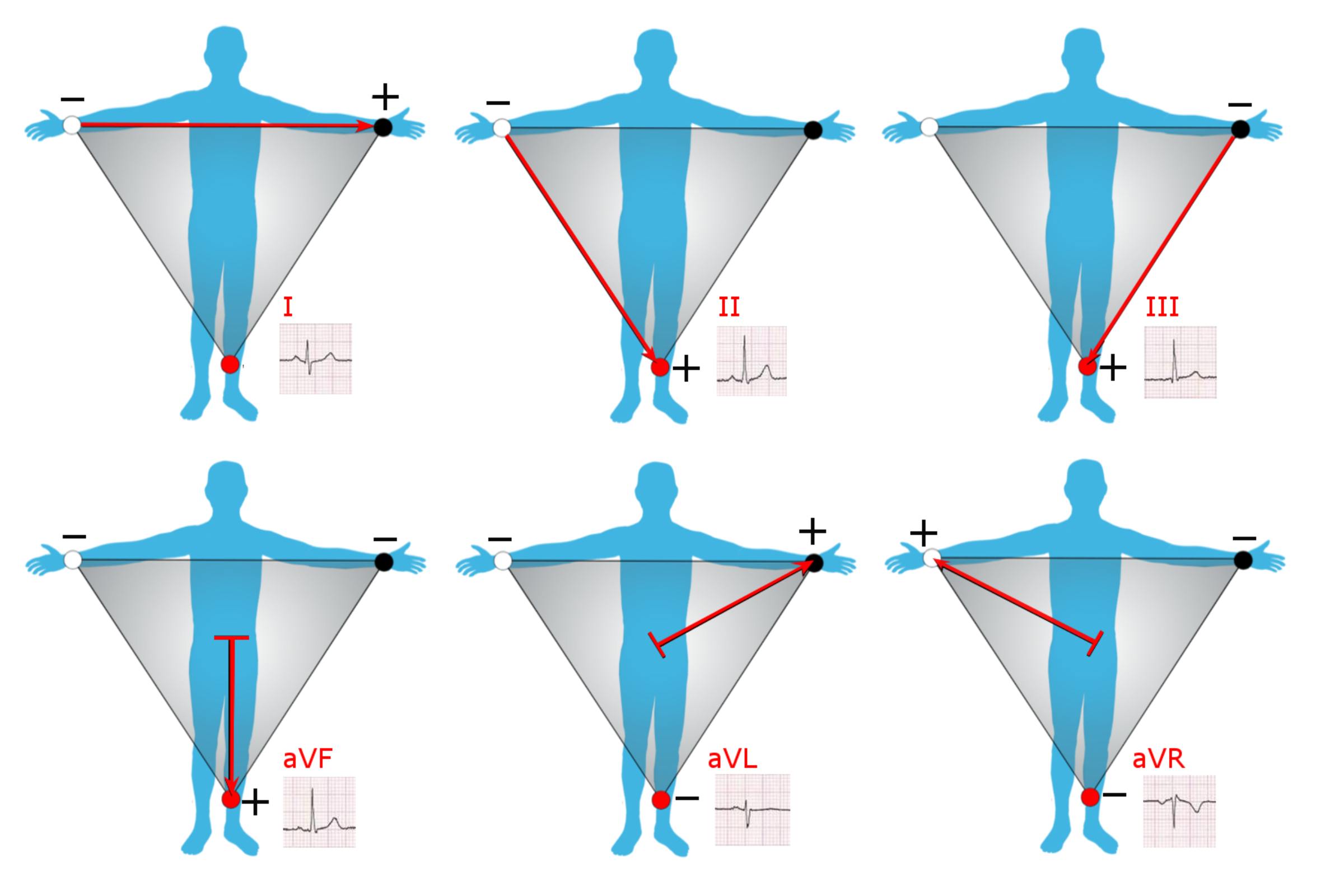
Lead I: This is a standard bipolar limb lead that measures the electrical potential difference between the right arm (negative pole) and the left arm (positive pole). The vector travels horizontally across the chest from right to left, primarily viewing the high lateral wall of the left ventricle.
Lead II: This bipolar lead records the voltage difference between the right arm (negative pole) and the left leg (positive pole). Because the heart’s normal electrical axis travels downward and to the left, Lead II typically displays the highest voltage P-waves and QRS complexes, making it ideal for rhythm monitoring.
Lead III: This bipolar lead connects the left arm (negative pole) to the left leg (positive pole). It directs the electrical view toward the inferior surface of the heart, working in conjunction with leads II and aVF to assess the inferior wall of the ventricles.
aVF: The label stands for “augmented Vector Foot,” a unipolar lead where the positive electrode is placed on the left leg. The reference point (negative pole) is a calculated average of the right and left arm potentials, allowing the lead to look directly upward at the inferior wall of the heart.
aVL: Meaning “augmented Vector Left,” this unipolar lead places the positive sensing electrode on the left arm. It views the heart from the left shoulder, providing diagnostic information about the high lateral wall of the left ventricle, often complementary to Lead I.
aVR: Standing for “augmented Vector Right,” this lead places the positive electrode on the right arm and views the heart from the right shoulder looking into the ventricular cavity. In a healthy heart, the electrical activity moves away from this lead, resulting in a predominantly negative (downward) deflection on the ECG trace.
The Physiology of the Frontal Plane Leads
The six leads depicted in the image—I, II, III, aVR, aVL, and aVF—are collectively known as the frontal plane leads. They provide a two-dimensional view of the heart’s electrical activity as if looking at the patient’s chest from the front. This system is built upon the principles of physics and volume conductors. The heart acts as an electrical generator, situated in the center of a volume conductor (the torso). By placing electrodes on the extremities, clinicians can detect the millivolt-level currents generated during cardiac depolarization and repolarization.
The first three leads (I, II, and III) are termed “bipolar” because they possess a distinct positive and negative pole. Invented by Willem Einthoven, these leads form an equilateral triangle around the heart, known as Einthoven’s Triangle. Einthoven’s Law states that the potential in Lead II equals the sum of the potentials in Lead I and Lead III (II = I + III). These leads are crucial for determining the heart’s electrical axis—the average direction of the wave of depolarization. If the heart is displaced or if the muscle is thickened (hypertrophy), the electrical axis will shift, changing the appearance of the waveforms in these leads.
The remaining three leads (aVR, aVL, aVF) are “augmented unipolar” leads. Unlike the bipolar leads, they do not measure the difference between two single physical points. Instead, they measure the potential at one positive limb electrode against a “null” reference point created by connecting the other two limbs. This reference point is known as Wilson’s Central Terminal. Because the signal from these leads is naturally small, the ECG machine augments (amplifies) the voltage by approximately 50% to make the traces readable, hence the prefix “a” in their names.
The primary physiological applications of these six leads include:
- Axis Determination: Evaluating the direction of the QRS complex in leads I and aVF helps determine if the heart’s axis is normal, left-deviated, or right-deviated.
- Localization of Ischemia: Grouping these leads allows for anatomical localization; for instance, II, III, and aVF view the inferior wall, while I and aVL view the lateral wall.
- Conduction Analysis: The morphology of the waves in these leads helps diagnose conduction blocks, such as hemiblocks (fascicular blocks).
- Chamber Enlargement: Voltage criteria in these leads are used to diagnose atrial or ventricular hypertrophy.
Analyzing Vectors and Polarity
To interpret an ECG, one must understand vectors. A vector is a quantity that has both magnitude (voltage strength) and direction. In the provided image, the red arrows represent the positive axis of each lead. A fundamental rule of electrocardiography is that when a wave of depolarization moves toward a positive electrode, the ECG machine records an upward (positive) deflection. Conversely, when the electrical wave moves away from a positive electrode, a downward (negative) deflection is recorded.
For example, the sinoatrial node initiates an impulse that spreads through the atria and then down the ventricles toward the apex. This dominant movement is generally downward and to the left. Consequently, Lead II (which has its positive pole on the left leg) usually shows a strong positive deflection because the current is heading straight for it. In contrast, Lead aVR (positive pole on the right arm) sees the current moving away from it, resulting in a negative P-wave and QRS complex. A positive deflection in aVR is often a red flag, suggesting incorrect lead placement (limb lead reversal) or specific pathologies like dextrocardia.
Clinical Utility in Diagnostics
The interplay between the standard and augmented leads provides a 360-degree view of the frontal plane, divided into 30-degree segments. This “hexaxial reference system” is vital for diagnosing complex cardiac conditions. While the chest (precordial) leads view the heart in the horizontal plane, the limb leads are superior for identifying inferior and high-lateral myocardial infarction. For instance, ST-segment elevation in leads II, III, and aVF is a hallmark sign of an occlusion in the right coronary artery or left circumflex artery supplying the inferior wall.
In summary, the derivation of the limb leads is a sophisticated application of bio-electricity. By utilizing the geometry of Einthoven’s triangle and the augmentation of unipolar signals, medical professionals can reconstruct the electrical activity of the heart. Mastery of these vectors—knowing where each lead “looks” and what constitutes a normal polarity—is the first step in the accurate interpretation of the 12-lead electrocardiogram.

